The mechanical design uses the design concepts of the largest telescopes.
- kinematic connections
- high stiffnes tubular structure with high damping
- deep beam structure
- light construction
- precise motion
- backlash free mechanical drive
- three image positions
- ruby bearings
- laser cut aluminum formed
- spherical truss connections
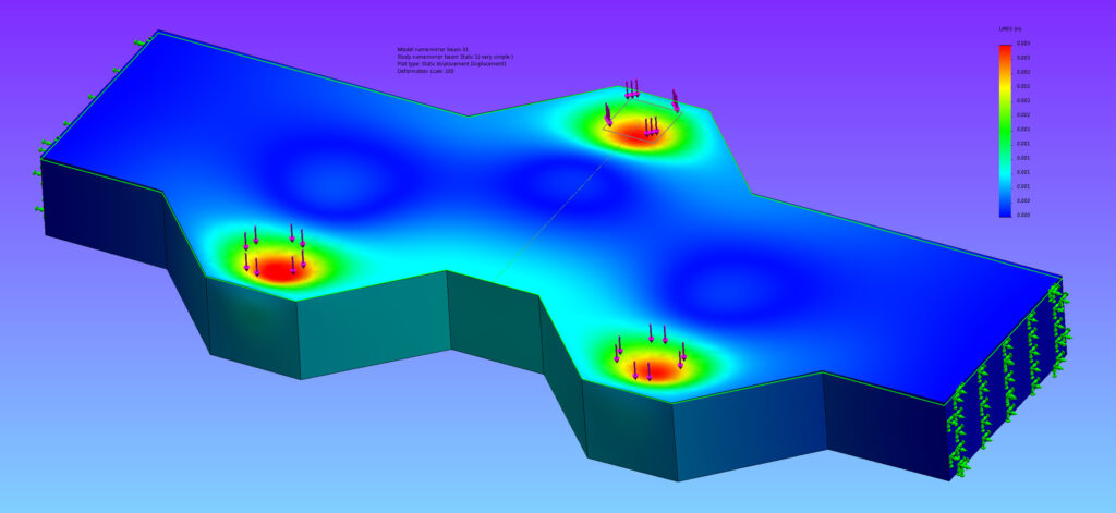
The main mirror must not deform more than 50nm under the force of gravity. The mirror is 81cm in diameter 4.1 cm thick at the edge. It weighs 41 Kg. It has 54 points of support. The mechanical system of teeters and triangle teeters is designed to apply force to minimize deflection. Never the less the mirror will sag between the contact points.
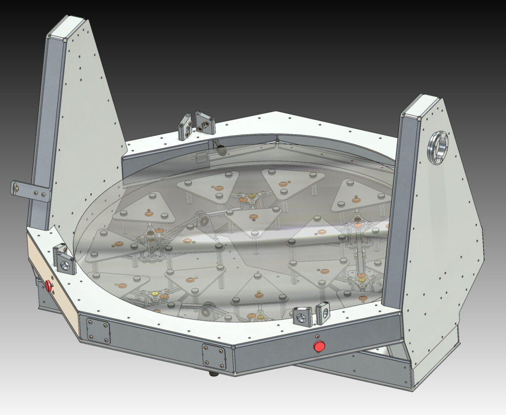
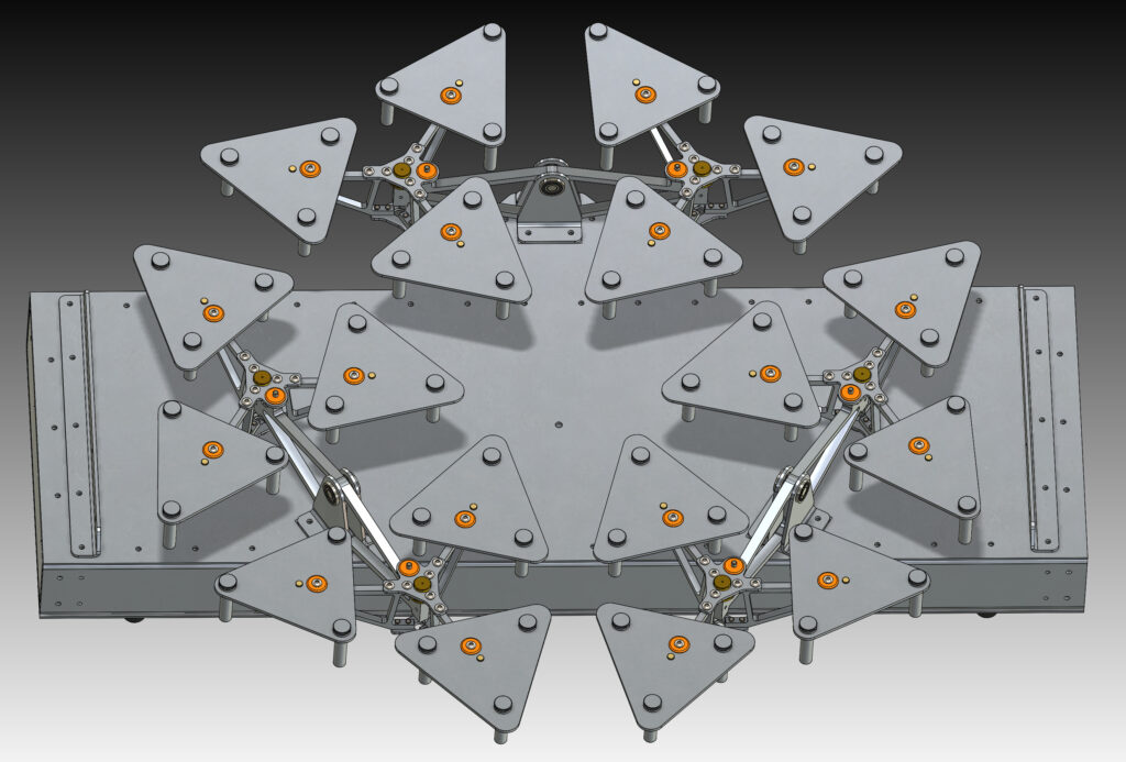
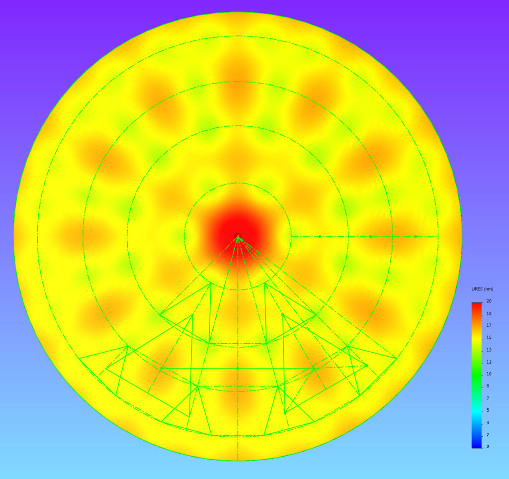
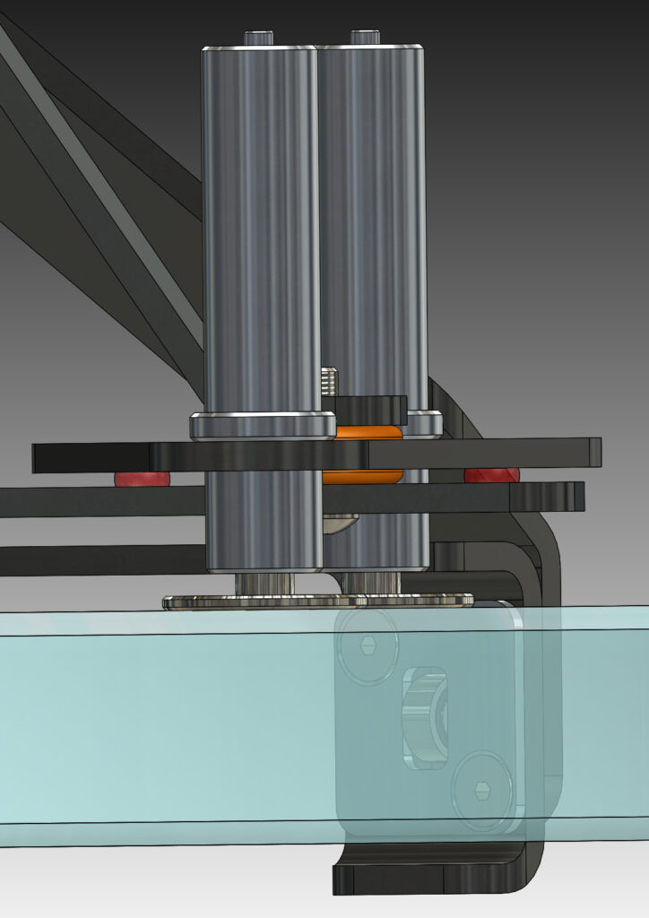
The mirror is held in place by lateral support system. There are 4 edge rollers at the bottom of the mirror, and two tension supports at the top. Ball bearings are used to minimize friction and distribute the forces. The support contacts are flexures that will not apply lateral force.
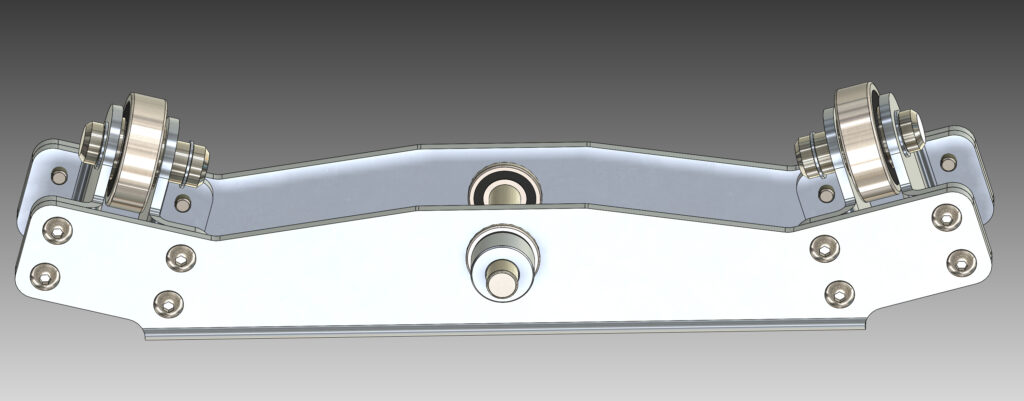
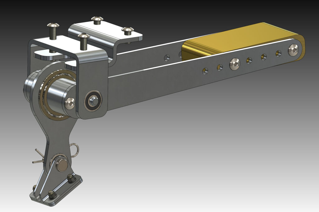
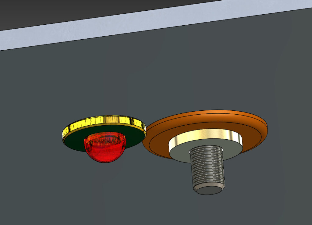
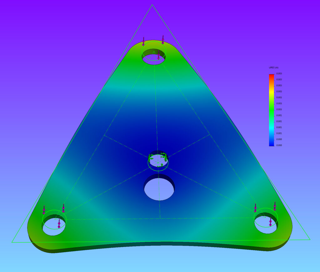
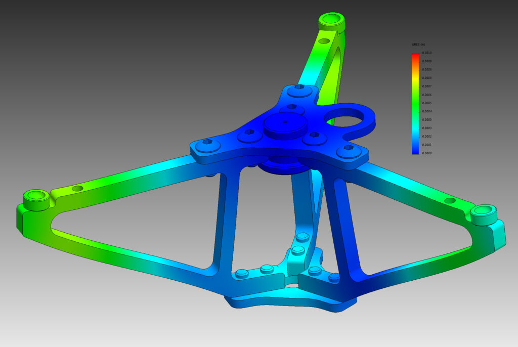
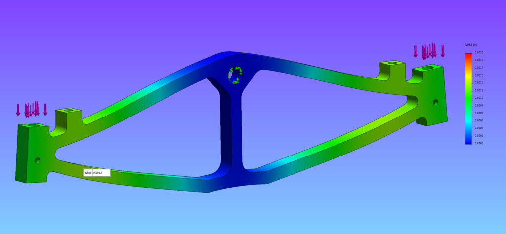
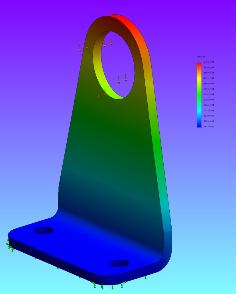
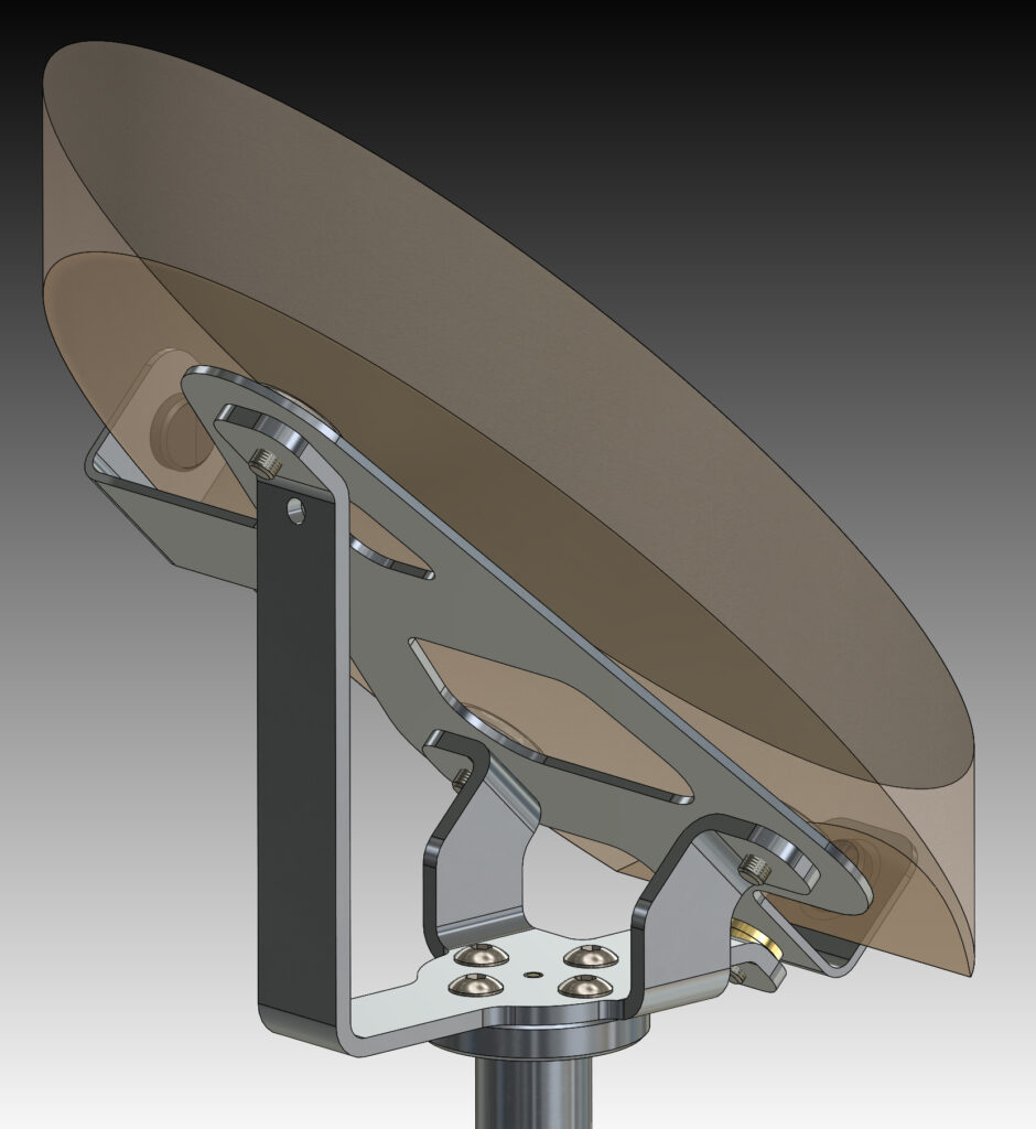
The miror supports are small important structural elements. There are four levels: contact small triangles, large deep triangle, large teeter and mirror beam. Each will deform under load. The total deformation should be limited to 0.010 inch. This will affect focus but not distrub the optical figure of the mirror. The small triangles rest on a small ruby sphere. A soft rubber grommet keeps the assembly in place. These triangles rest on a larger deep triangle that pivots on a steel tooling ball. The height of the tooling ball is adjustable with a set screw. These triangles rest on a teeter that pivots on ball bearings. The teeter is supported by the mirror beam.
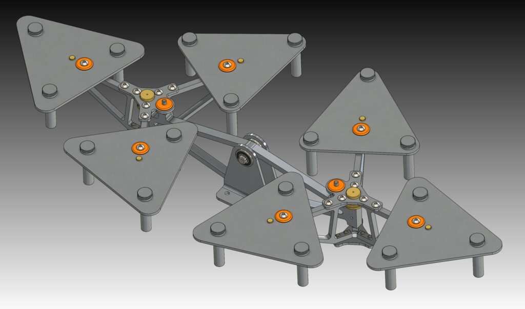
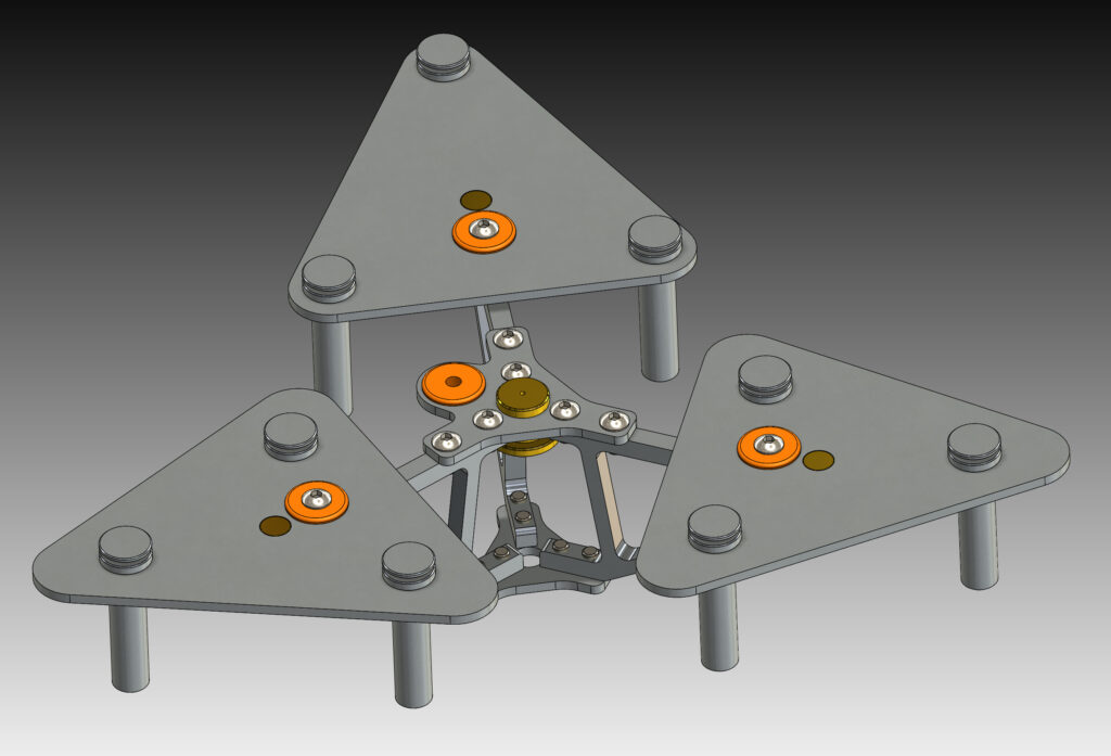
The mirror box is the structure that supports the mirror and unites the mirror ring and pivot arms. It pivots on large 110mm bearings.
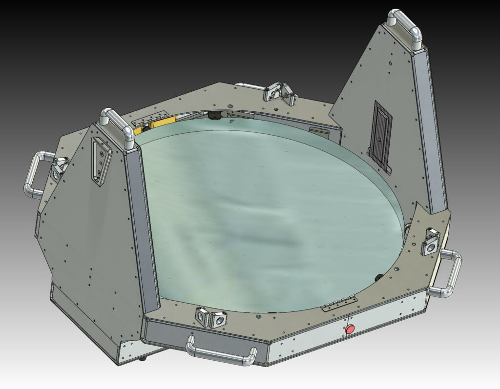
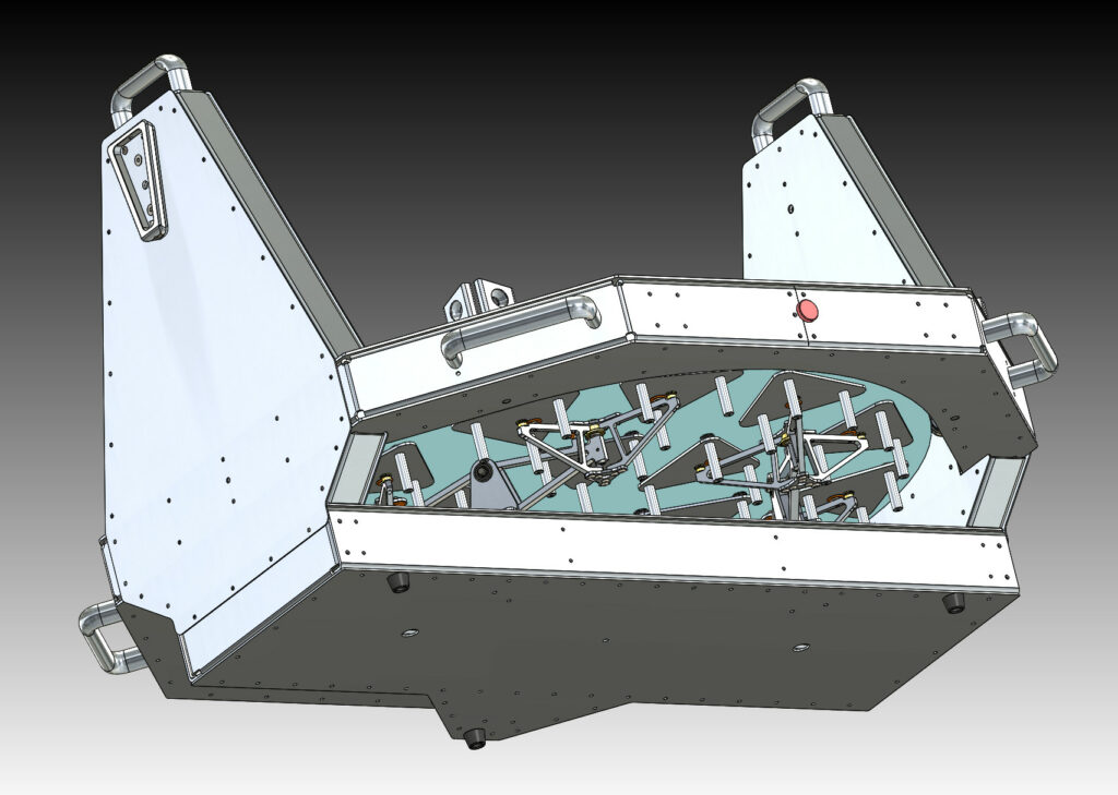
The mirror rests on mushroom shaped flexures. These bend easily in the plane of the mirror. They are stiff in the axial direction. This eliminates lateral forces at the contact points on the back side of the mirror. After inital assembly a U shaped tool is used to center each ofthe 54 flexure supports.
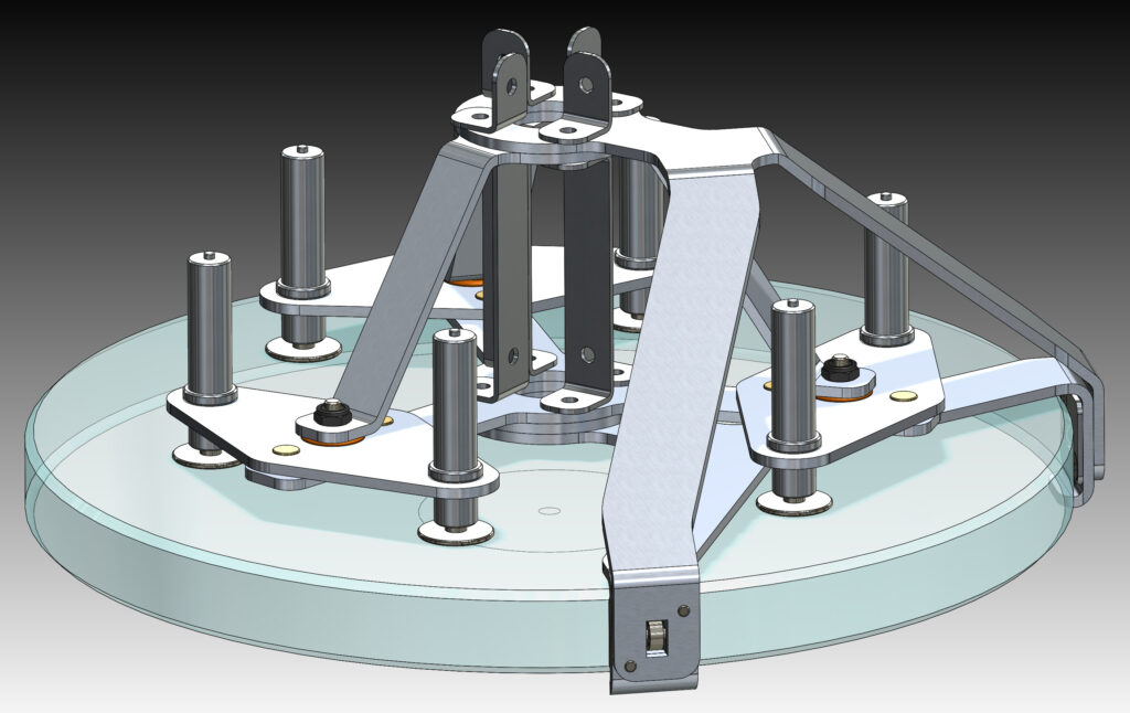
The thin secondary mirror is 12 inch, 30cm, in diameter and 1.0 inch, 25mm, thick it is made of fused quartz. It must be supported at 6 points on the back surface. The six contact pads are made from invar, that is bonded to the back side of the mirror. The force on each point is identical, by virtue of teetering pivots. The teeter parts rest on two ruby balls, and is retained by a soft silicone rubber grommet. It is important that the alignment of the telescope is maintained at all attitudes. The lateral forces are applied by ball bearing rollers at the lower edge of the secondary mirror.
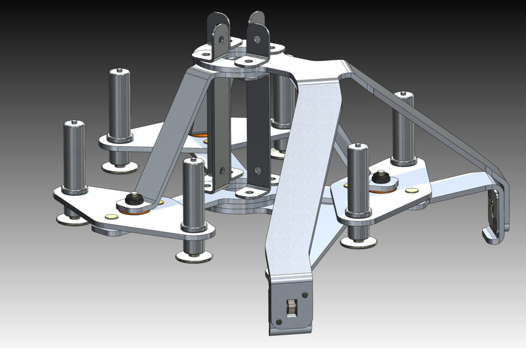
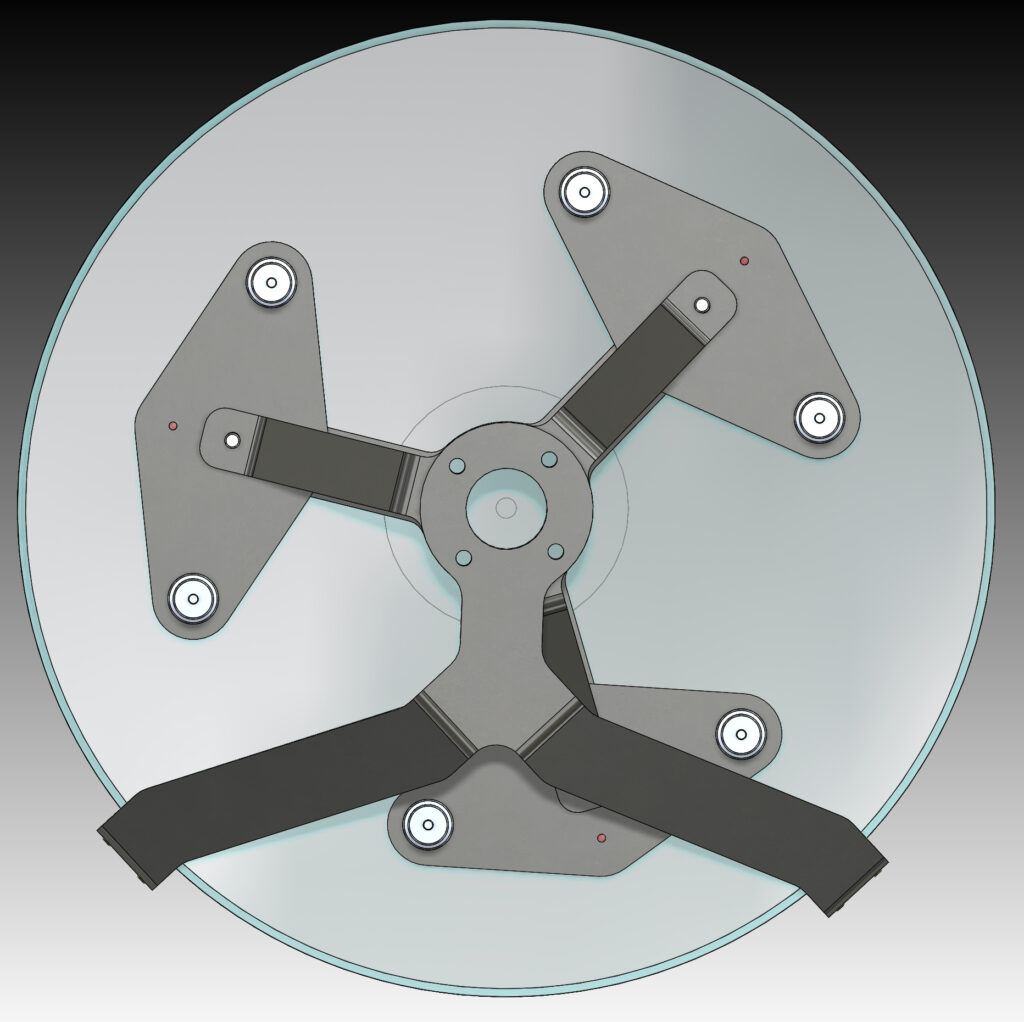
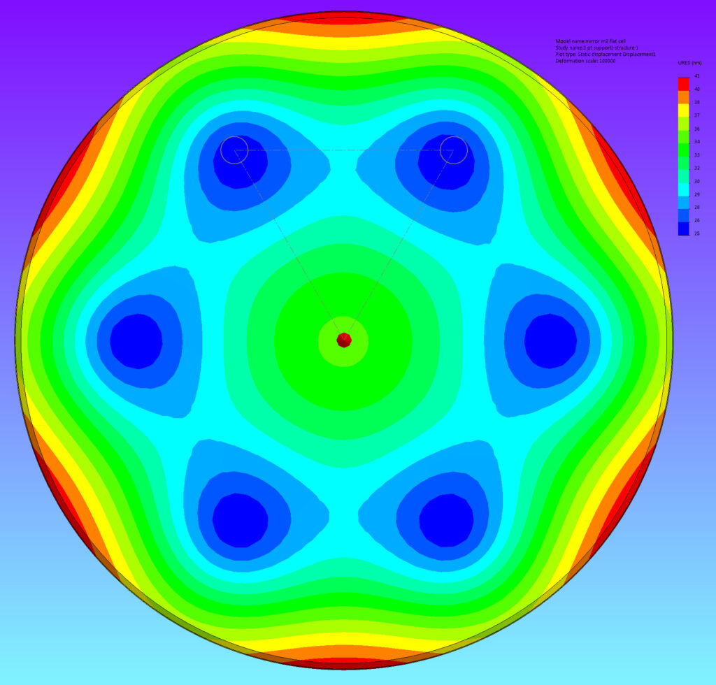
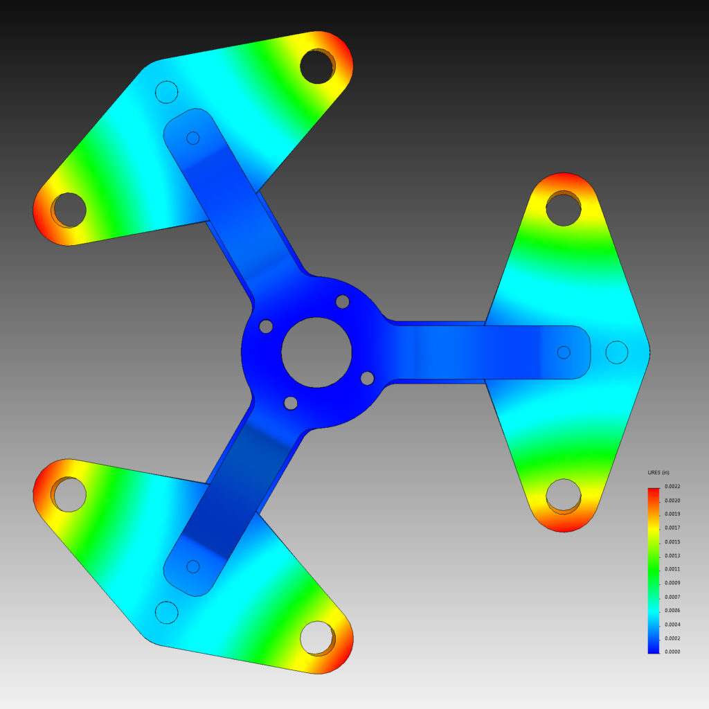
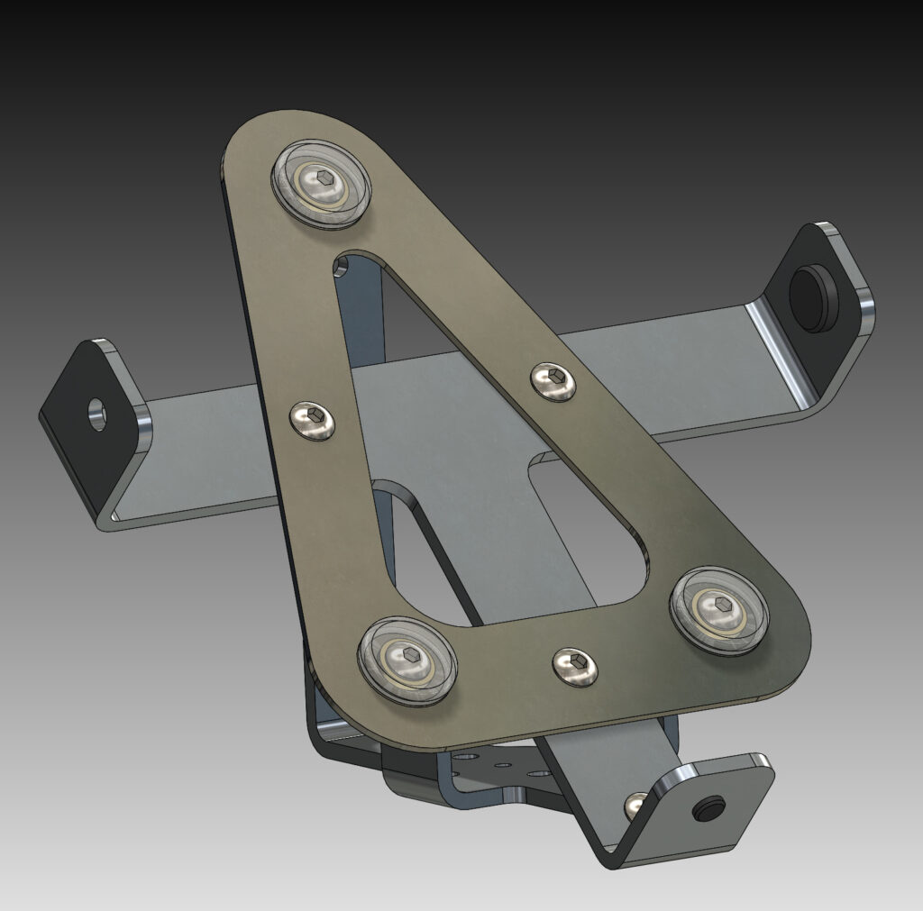
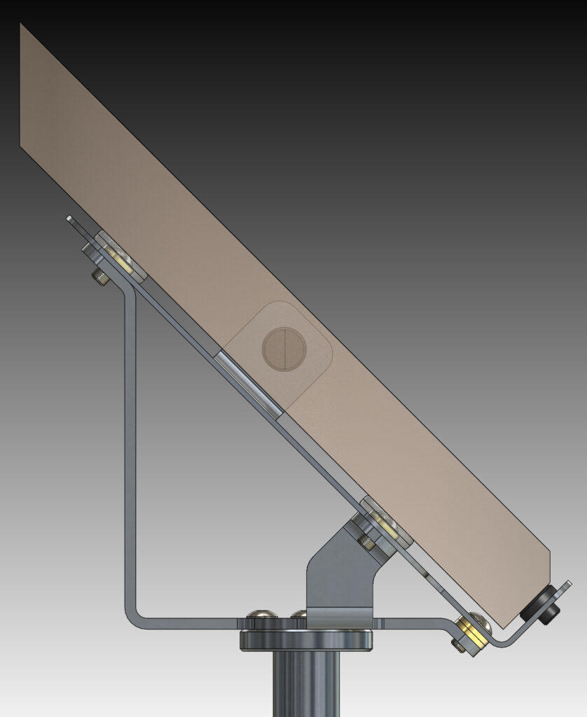
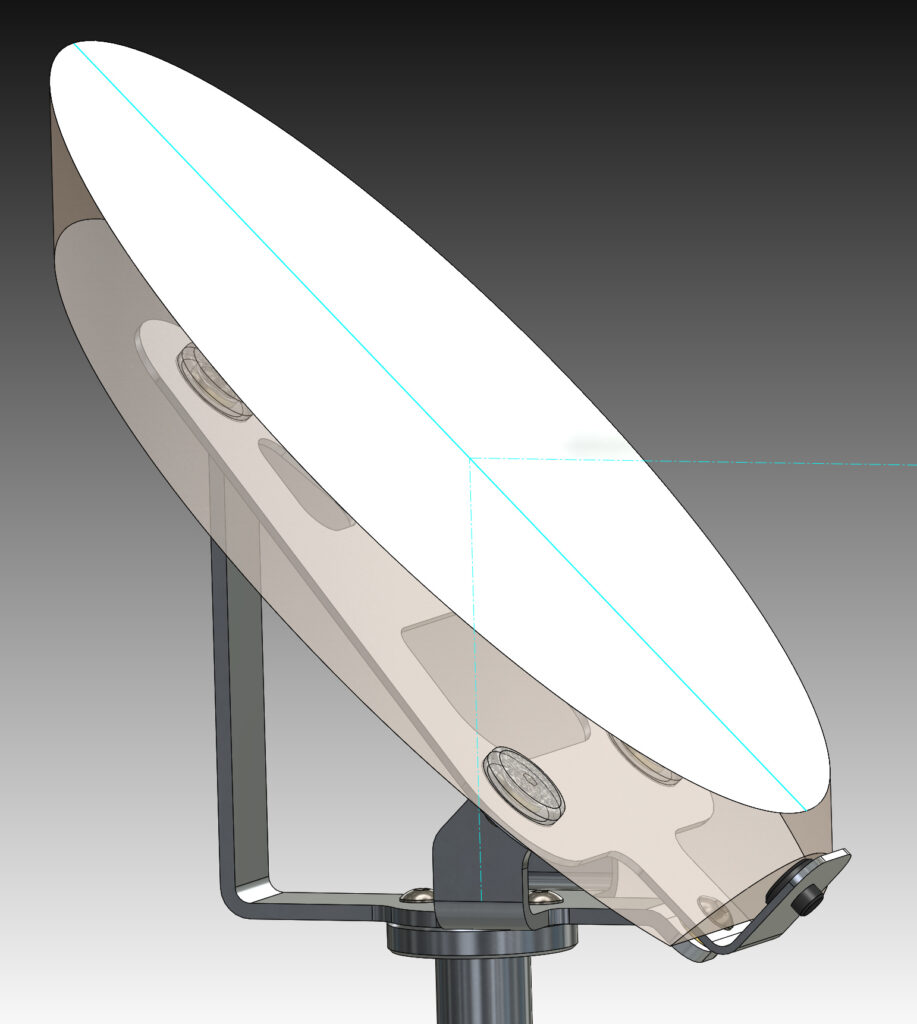
The final mirror is a diagonal that directs the light to the eyepiece at the side of the telescope. This mirror has a elliptical shape with a minor axis of 6.0 inches, 15cm, the thickness is 1.0 inch, 25mm, it is made from fused quartz. It is supported at three points. It is bonded at the support points with a blob of silicone rubber. The support points are positioned using an invar plate.
The truss tubes have spherical ends.They are engaged by activating a winged DZUS fastener. The lower fittings fit closely so the truss tubes can be installed easily and not move too far. The hula ring is a light ring shaped fitting that allows easy connection of the truss structure. When all of the truss tubes are connected the telescope has a solid structure. The nose piece is positioned on 12mm ruby ballls and held in place using draw latches.
The base of the telescope is a hexagonal plate with three rigid steel feet. At each foot is a pair of ball bearing rollers. The lower surface of the azimuth bearing ring forms a precise plate bearing 46 inches in diameter. There are three additional load sharing bearings to reduce the deformation of the azimuth bearing ring. The goal is a bearing with 1 arc second repeatability.
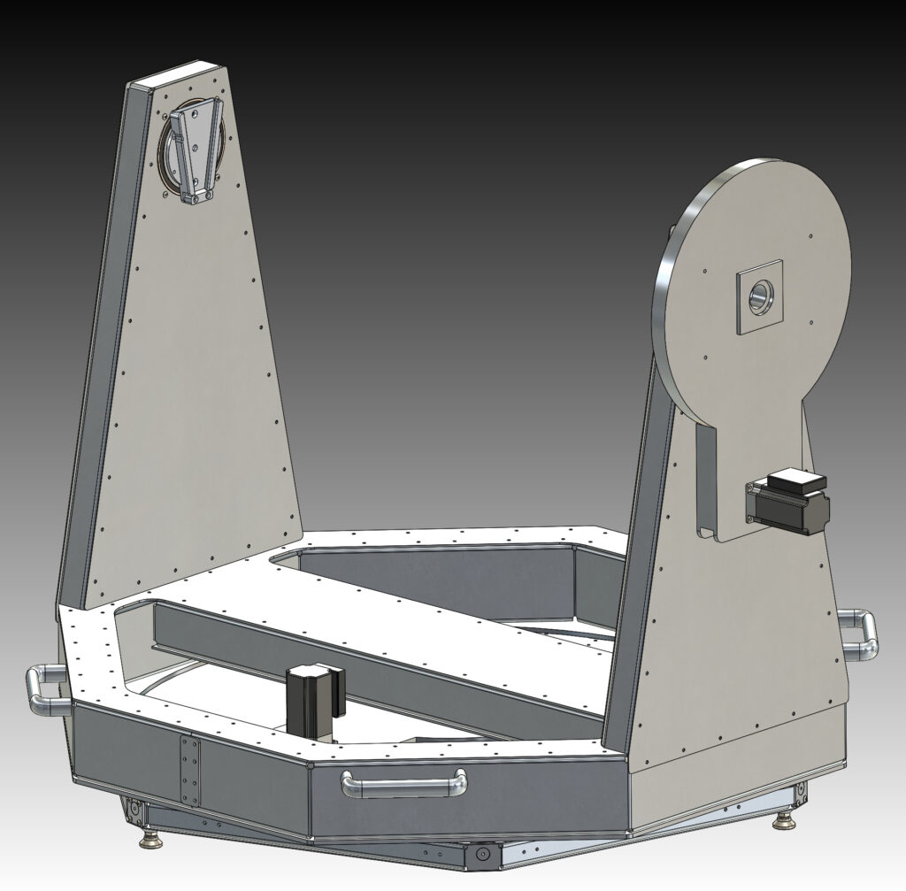
The drive system is sandwiched between the base and the azimuth bearing ring. It applies only rotary torque. A load limiting clutch protects the precise drive gears and allows smooth manual motion.
The rocker box is the combination of the azimuth bearing ring and altitude pivot arms and altitude bearings. The altitude bearings are in preloaded pairs and have a 110mm inside diameter. The altitude drive system is on one side away from the observer. The altitude drive force is transmitted by a finely fitted keystone tapered fitting.
The telescope tube assembly balances nearly at the altitude axis. This allows for smoother manual motion minimizing stick slip friction.